![]()
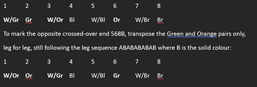
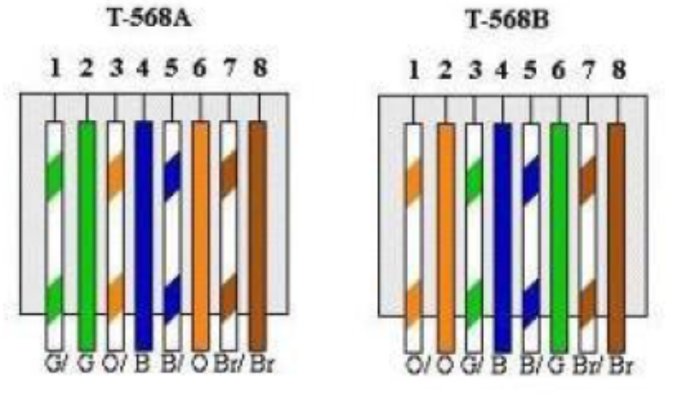
When viewing left to right pins 1-8, the pair legs – even if split colours, are legs AB AB AB AB AB
where B legs are SOLID colours.
The blue pair legs on Pins 4+5 seem reversed (legs BA) because for voice, in an RJ11, the B legs (single colour – no white) are all on pins 1, 2 and 3 (when working for BT installing phone cables, I always remembered “B legs 1,2,3”), with the blue pair in the middle of the connector, so are on pins 3+4, which in an RJ45, the middle pins are pins 4+5, with the Blue pair B leg first (pin4 – blue: pin5 White/Blue).
You should not have to think about Power over Ethernet voltages on any cable pins because:
“In Power over Ethernet (PoE), the pins that supply voltage depend on the PoE Mode (also called Alternative) being used by your equipment. The IEEE 802.3af/at standards require "Powered Devices" (like your IP camera or VOIP phone) to be able to handle both Mode A and Mode B automatically.”
The Blue and Brown pairs do not change between 568A and 568B positions.
The 568A starts with the Green pair pins 1+2 as legs A+B so W/Gr, Gr.
Start by drawing the connector pin:
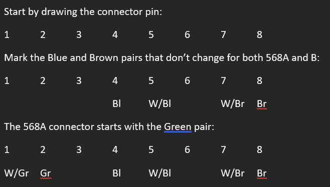
This only leaves the Orange pair to add, and as the pins follow leg sequence ABABABAB, pin 3 must be W/Or so pin 6 is Orange: