This old radio was £20 but good condition in a dog charity store. It has a full valve compliment so seemed worth the risk. I don't have much test gear these days, so did what checks I could with what I have and no oscilloscope. I decided to go ahead and do what I can to get this thing in working order at minimal cost based on those results. As I'm not so experienced on valve radios as I am on valve amps I took many pics before detaching any wires to test the mains caps and transformer to see if it was worth proceeding further:
vidor_chanson_cn349_radio_1946_sm.pdf
I checked the duff states of the capacitor can marked 8uF and 16uF, bubbled mains filter caps for interest (16uf and 24uF on the schematic):


The cap leads may have been connected to the wrong sides of the choke too - I'll have to check before the new 22uF caps arrive, not that it matters as I have two the same values ordered. I don't have terminal tie strips so still thinking how I'm gonna connect the caps to the rectifier wires...

As an aside, here is a good explanation of why 50 Ohms coax is used as a compromise between 30 and 75 Ohms for price, lowest impedance losses and power handling of radio signal Tx/Rx, when thinking about getting radio signals to this unit as it does not have it's own aerial, so I will look at diff types of aerials to feed it, from a simple loop of wire to RG6 coax and/or F7 coax connector from the wall sockets etc:
... so WHY some test gear historically has or expects to connect to a 50 Ohm load :
I took readings for some components and did some calcs for what to expect from this thing based on present tube types power max ratings and the windings ratings:
Total Secondary Windings Power
240V x 0.06A = 14.6W +
4V x 2.5A = 10W +
6.3V x 3A = 19W
= 44W
Total Primary Winding Current for fuse is about:
40W / 240V = 1/4 Amp
Big Iron windings:
Primary: 29 Ohms, 108mH
Secondary: 587 Ohms, 9.4H
Rectifier Heater Winding: 0.5 Ohms, 0.01 mH
Valve Heater Winding: 2.18 Ohms, *no H measure
Audio Transformer: 362 Ohms, 8.2H
Choke: 380.6 Ohms, 12H
Importance of visual inspection before even thinking about power up !:

I will use my dim bulb tester for the next tests. If you do the power calculations, you will understand why a lower wattage INCANDESCENT (AC resistive/reactive) bulb limits the current to the device under test in the event of a short circuit in the unit, so also limits the voltage applied to the unit to hopefully not overstress old capacitors too much while they may be reforming to a temporary working state:
P = IV
25W incandescent bulb:
25W/ 240V = 104 mA
40W incandescent bulb:
40W/ 240V = 167 mA
100W incandescent bulb:
100W/ 240V = 416 mA mA
150W incandescent bulb:
150W/240 = 0.625 mA
https://www.youtube.com/watch?v=pqTFaK0G5-c
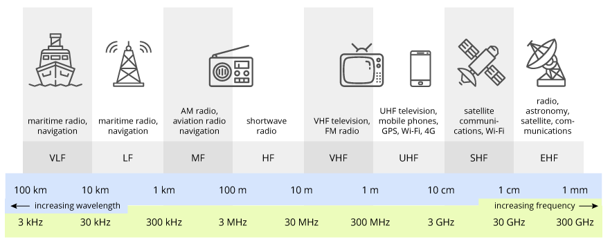
Short Wave ranging from 200-600 meters, and the wavelength of the HF is 10 to 100 meters.
Medium Wave, also known as intermediate frequency (MF), that is, radio waves with a frequency of 300KHz-3MHz.
Long Wave, between 150KHz-284KHz as the broadcast spectrum is used, the wavelength is concerned, it is about 1000 to 2000 meters.