I spent ages - as usual for me! - arsing about and getting nowhere with this circuit (and my crappy Hantek DSO 5102P scope and it's usual lockup and odd behaviour type hassle, hopefully improved after a firmware update!) from page 109 of GC Loveday's Electronic Testing book - should have been straight forward right - as easy as a circuit gets?!:
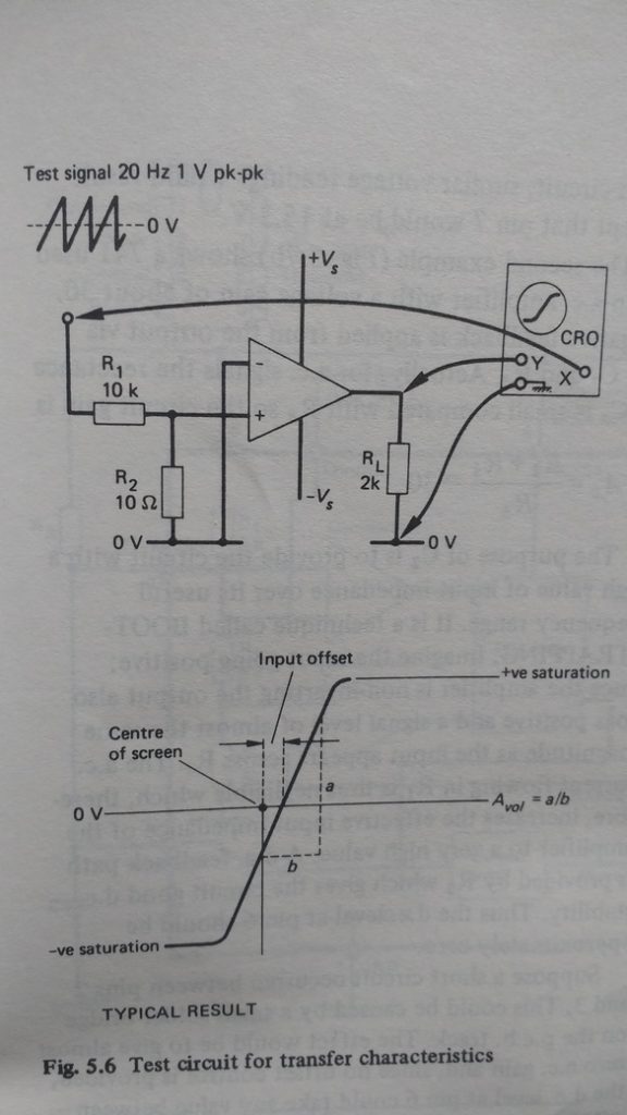
There is no Y component from this circuit as pin 1 out is grounded by the pull up resistor so has no amplitude no? I'm wondering if the +/- invert signs are error switched - though the output pin 1 is fixed the same as the inverting pin 2, with the input at non-inverting pin 3 should still work eh?But, I only got a flat line in XY mode at a 20Hz ramp so don't know why this doesn't work - even at 10Hz or 1kHz sine/ramp/triangle...nothing?
Do you have to have the sig gen gain cranked up more...as I found I was doing below for the working versions??
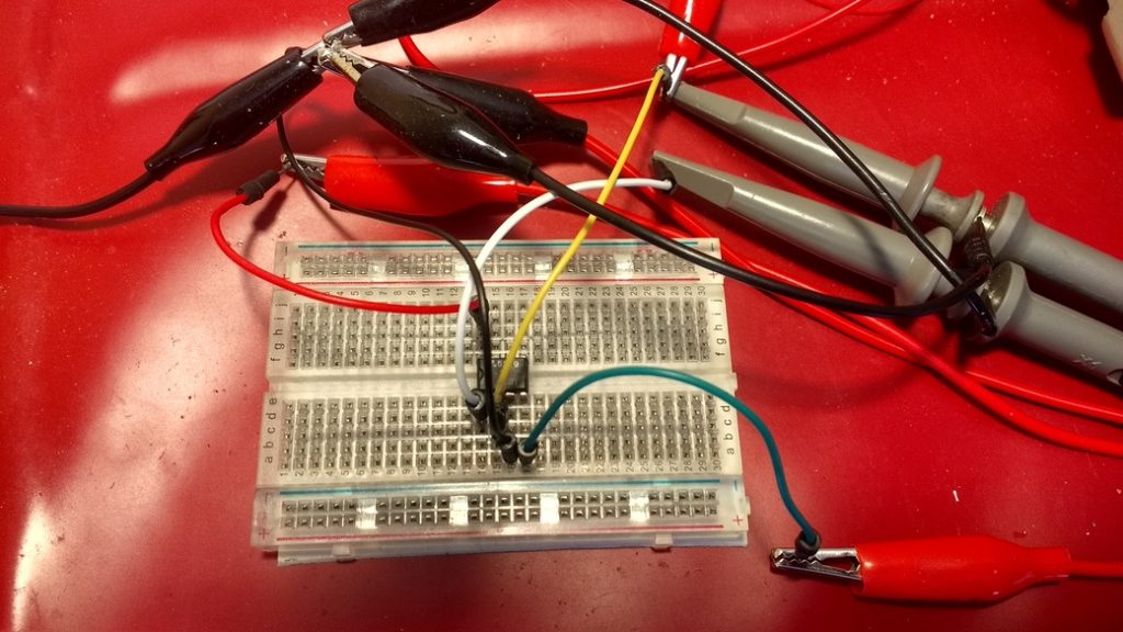
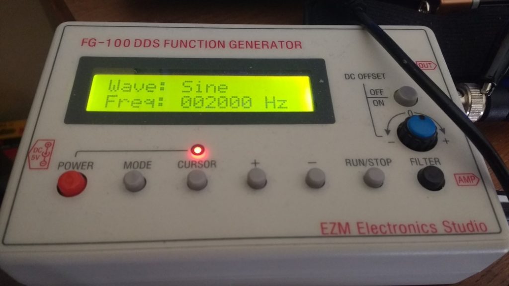
I finally made some progress with the simplest way possible to view the op amp's- output, from this guy, by using the inverting input instead with the non inverting input at ground:
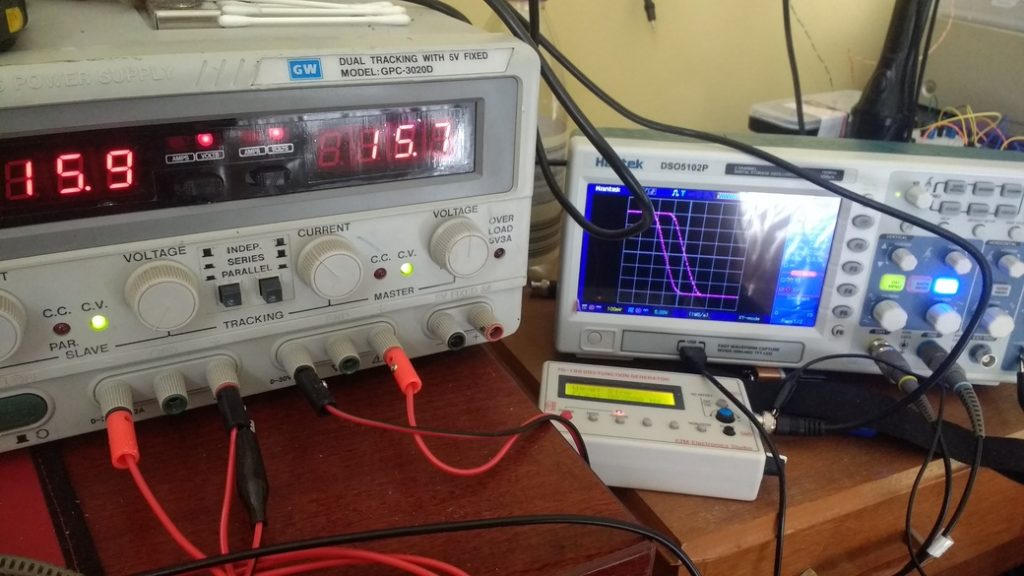
This shows NO components required - just a 1-2Vpp sine wave (2kHz worked best for me) in and out (pins 2-; 1 out; 3+ to ground of a +/- 15.7V supply) to give the clearest view of the slope at my scope's settings).
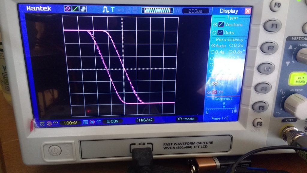
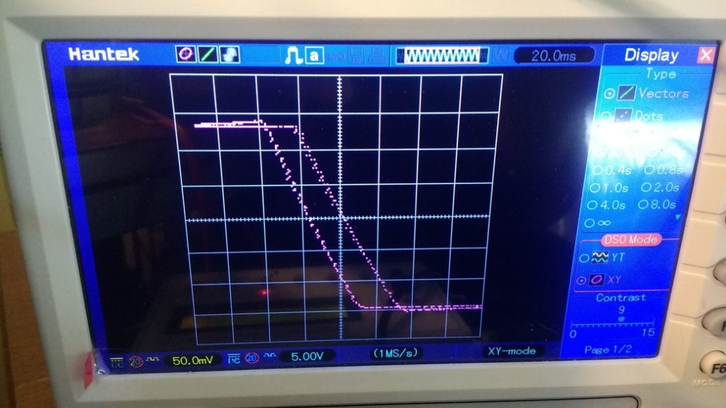
This gave me the same as him at least - digital scopes are crap in XY mode display, at best - and after trying different wave forms at different cycles/sec I found 2kHz best:
This output is from the M5219P tone amp from the Technics V1X - total symmetry as you'd expect.
This method can be used to test an op amp quickly on a bread board without building a circuit board - if you lost your tester you already built..?
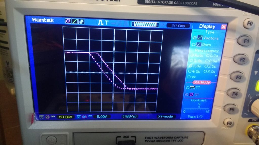
LM358s at 20Hz looks like:
After changing Vcc to pin 7 and output to pin 6, the 741 op amp at 20Hz looks like:
Arduino, Amps, Kits etc.