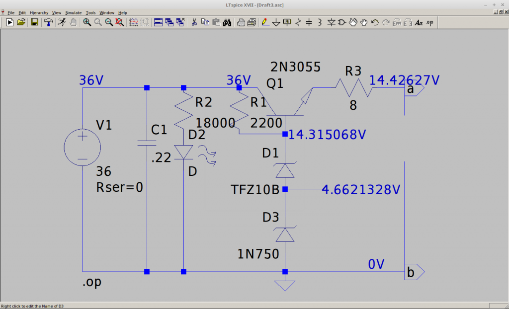
From the Sony EX50 Specs, 110W RMS continuous into 6 ohm, TAM transformer, has a 28V RMS winding, giving about a 36V peak DC ouput after rectification in reality (now built, it shows this).
The continuous AC speaker output is 110W/V = 4A Max. Should be OK to charge a car battery, not great. Will need a current limiter to not pull the windings hot, so for now,- a limiting resistor in the output..?
I have removed the rectifier from the amp also, and will use a 2035 or similar for the transistor, with a 14V Zener (allows 0.7 baseV for 13.3V across battery).
![12V Battery Charger Circuits [using LM317, LM338, L200, Transistors] | Homemade Circuit Projects](https://www.homemade-circuits.com/wp-content/uploads/2019/07/TIP122-simplest-12V-battery-charger-circuit.png)
The RMS windings are:
0, 28, 56, 10.5V, 1, 7V.
Use the 10V winding with a rectifier cap and diode for a 6V driver for the LED bank from torch.
Silicon NPN Power Transistor BU105
DESCRIPTION -·High Voltage-VCER= 1300V(Min.) -·Collector-Emitter Saturation Voltage-
: VCE(sat)= 5.0V(Max.)@ IC= 2.5A -·Minimum Lot-to-Lot variations for robust device
performance and reliable operation
APPLICATIONS -·Designed for use in line operated B&W(19 and 20 inch 110℃
deflection circuits ) or color ( 11 and 14 inch 90℃ deflection
circuits TV receivers. ABSOLUTE MAXIMUM RATINGS(Ta=25℃)
THERMAL CHARACTERISTICS
SYMBOL PARAMETER MAX UNIT
Rth j-c Thermal Resistance,Junction to Case 2.5 ℃/W
VCBO Collector-Base Voltage 1300 V
VCER Collector-Emitter Voltage
RBE= 100Ω 1300 V
VCEO Collector-Emitter Voltage 750 V
VEBO Emitter-Base Voltage 5 V
IC Collector Current-Continuous 2.5 A
PC Collector Power Dissipation @TC= 90℃ 10 W
TJ Junction Temperature 115 ℃
Tstg Storage Temperature -65~115 ℃
---------
BU133
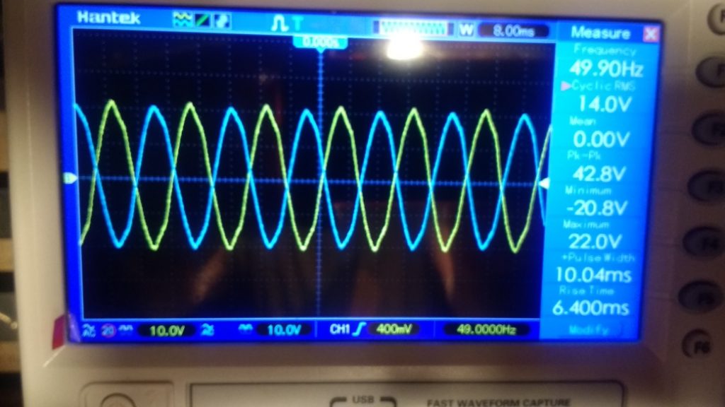
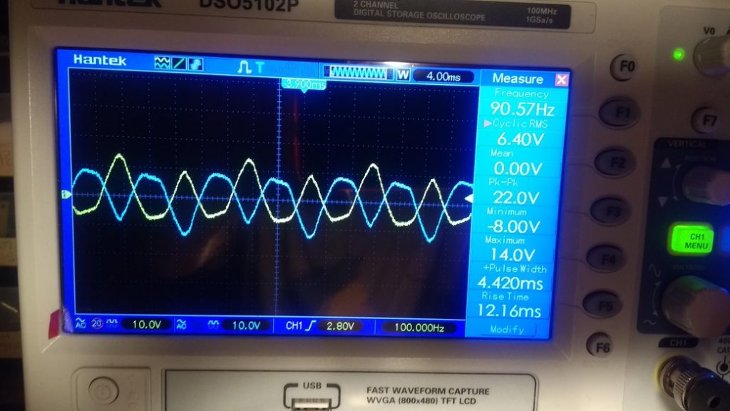
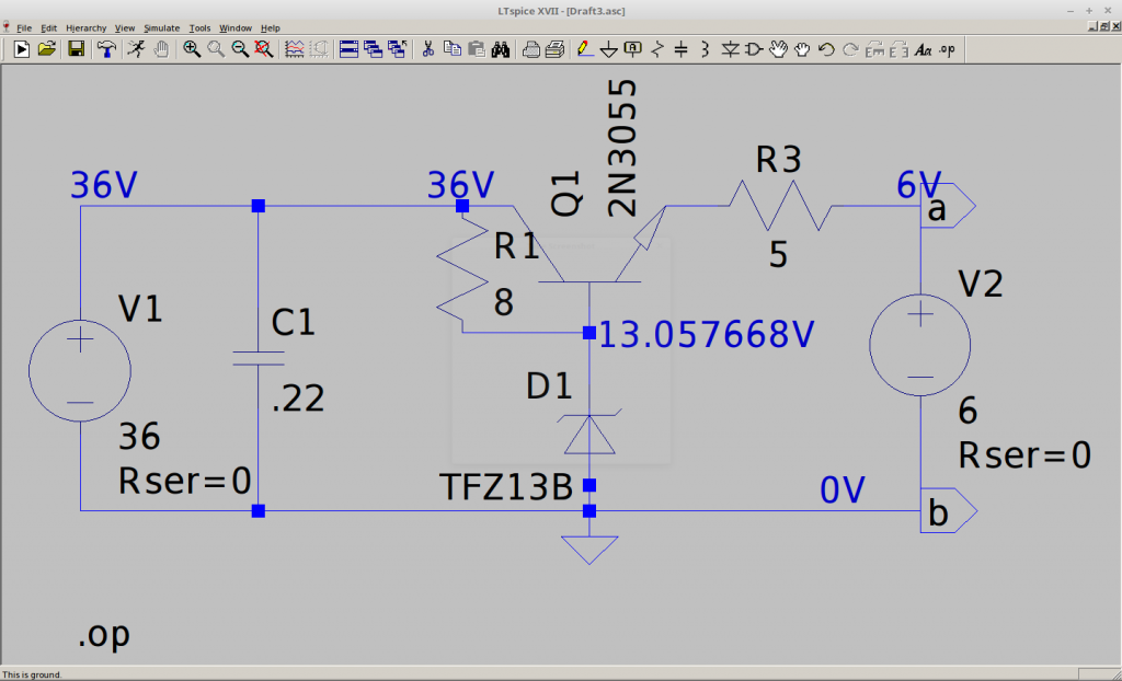
The bumpy DC at 100Hz and the rectified 36V after a 50V cap added:
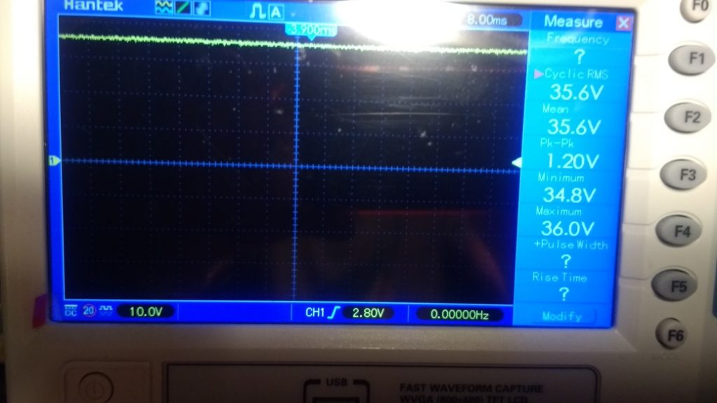
Scope measures 36V DC so assume that is right, I need 36-14V Zener = 22V to "lose" above the transistor/zener, but I don't know the Zener's max current rating...assume 5W max
https://stevepedwards.today/vetco.net/products/13-0-volt-5-watt-zener-diode-nte5128a
5W/14V = 0.35A Max thru Zener, so max through resistor/zener line = 0.35A
NOPE! The Zener does not dissipate anything like this - must not be 5W rated...no info on the 5Zs13A..
need a hi wattage variable pot to measure output current.
It needs to take max current of Zener rating = 0.35A x 8 ohm = 2.7W, so a 5W, 8ohm resistor required for the Zener voltage divider - got that.
The output resistor needs to limit a short circuit current to 3A (max transistor current) at full 14V output =- 4.6 ohm = 65Watt capability!!
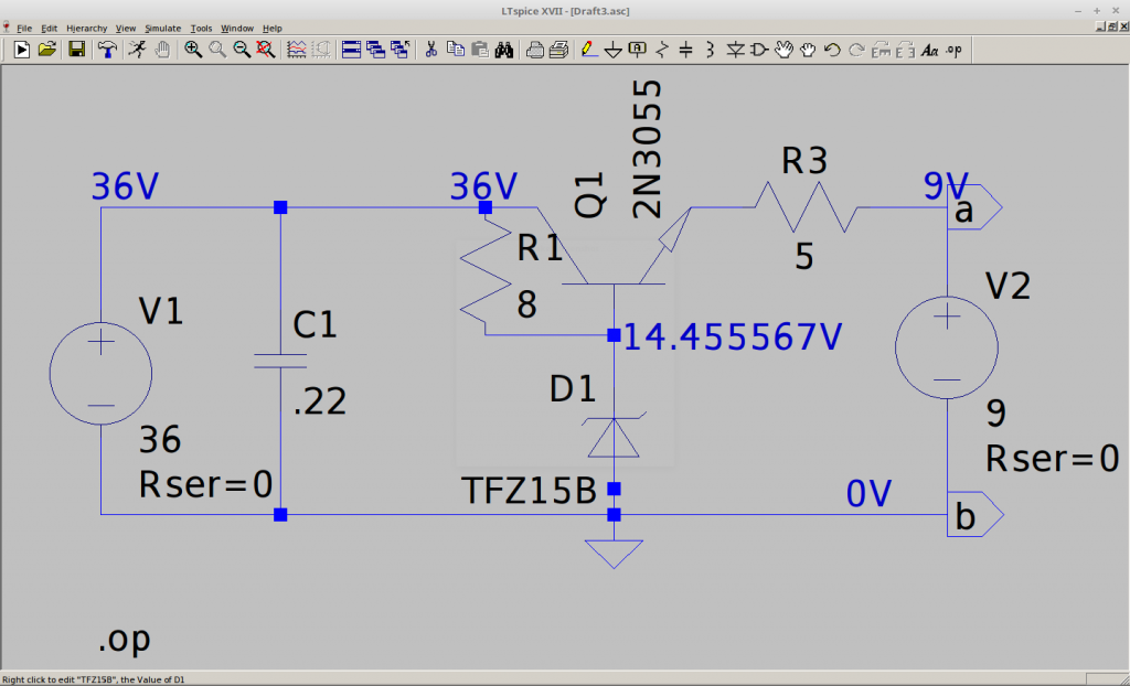
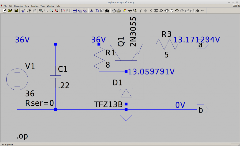
Using a 15V Zener in Spice, something like?:
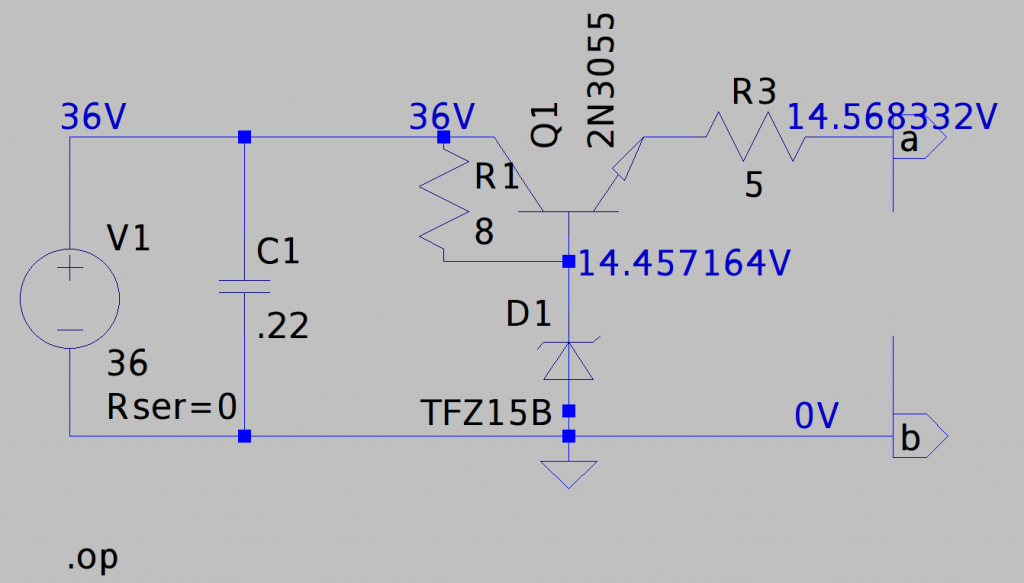
A flat battery at say, 9V would represent a PSU at the output, showing something like an amp drawn for charging at these values:?
--- Operating Point ---
V(n003): 14.4556 voltage
V(n001): 36 voltage
V(n002): 13.9629 voltage
V(a): 9 voltage
Ic(Q1): 0.966539 device_current
Ib(Q1): 0.0260375 device_current
Ie(Q1): -0.992577 device_current
I(C1): 7.92e-012 device_current
I(D1): -2.66702 device_current
I(R3): -0.992577 device_current
I(R1): 2.69305 device_current
I(V2): 0.992577 device_current
I(V1): -3.65959 device_current
Very flat at 6V would pull 1.5A:
V(n002): 13.9204 voltage
V(a): 6 voltage
Ic(Q1): 1.531 device_current
Ib(Q1): 0.0530815 device_current
Ie(Q1): -1.58408 device_current
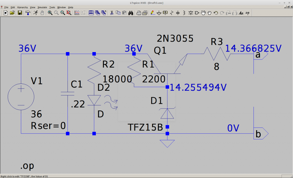
No 14.5V Zener in spice, but changing to a 13V Z and 6V flat battery?:
V(n002): 12.5431 voltage
V(a): 6 voltage
Ic(Q1): 1.26917 device_current
Ib(Q1): 0.0394515 device_current
Ie(Q1): -1.30862 device_current
For no load:
This is drawing WAY too much current - mistakes in maths, so the Zener is HOT!
To limit the Zener current for a 1/4W resistor value, 0.25W = (36-13V) x I
0.25W/(23V) = 0.01A
23V / 0.01A =2116 Ohm resistor required = 2.2K, 1/4W at 36V PSU
Gives a sim of:
V(n003): 12.8808 voltage
V(n001): 36 voltage
V(n002): 12.992 voltage
V(a): 12.992 voltage
V(p001): 0.786398 voltage
Ic(Q1): 9.25548e-009 device_current
Ib(Q1): -9.25324e-009 device_current
Ie(Q1): 0 device_current
I(C1): 7.92e-012 device_current
I(D2): 0.160062 device_current
I(D1): -0.0105087 device_current
I(R2): 0.160062 device_current
I(R3): 0 device_current
I(R1): 0.0105087 device_current
I(V1): -0.170571 device_current
The ON Hi Bright LED is limited to >0.002A by a 18k Ohm,this works so far:

Need to test under load now..I need a 14-15V Zener, but can try adding 2 x 0.7V diodes in series to get the extra 1.4V or so..?
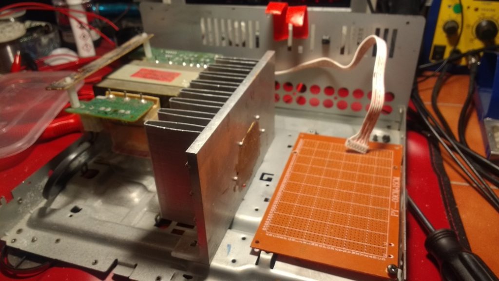
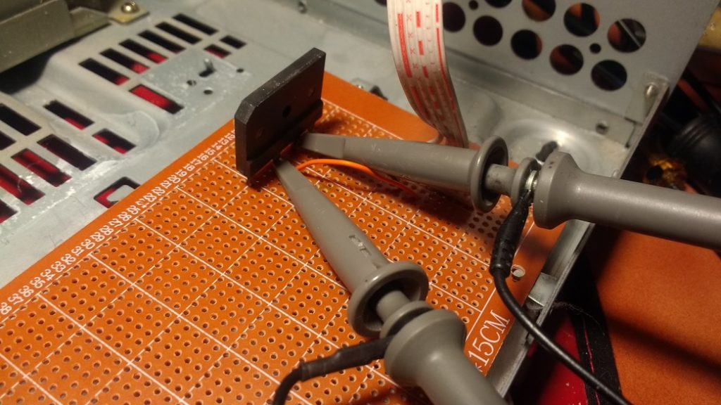
With just the 8 Ohm, 100W limiting resistor, the IBM368 test transistor gets to hot at only 0.7 Amps...not much good...only 10 times more current required!! ( The 10A socket on my BT meter divides by 10!)
With the 100W resistor in 4 ohm parallel at the output on the BT meter normal Amp socket, the current reads the same as the GW PSU amps display, and the circuit pulls 0.65A at 18V in series (36V total). The BU133 transistor needs the heat sink badly at this current, too hot to touch.
The output voltage is only 12.6V, not enough to feed a battery with barely half an amp.
A 15V Zener shows:
More research needed for what load a real car battery would represent across the output, and safety foldback circuitry. In practice, this circuit is useless so far.
A trick from YT circuit radiofun232, adding diodes to up the Zener voltage:
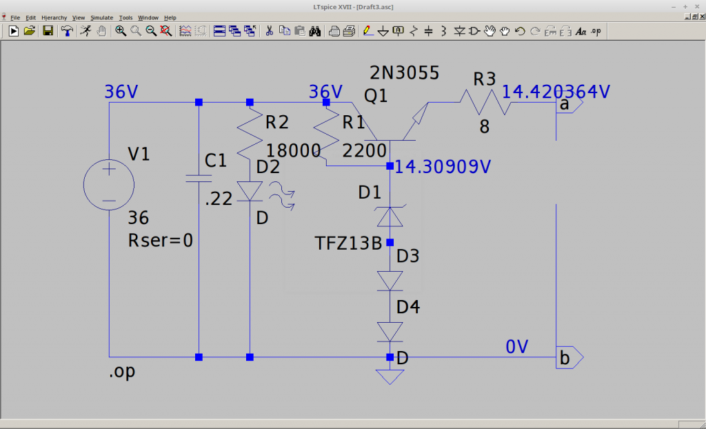
2 x 1N4007's should do it? AH,they change the voltages with changing load! Just use another smaller Zener, a 3.3 added to the 13 should do, but you have to edit the Spice Model parameters...or a 10V and 4.4V:
https://www.eevblog.com/forum/beginners/zener-diodes-in-ltspice/